
ZG4
Test Interface for Dielectric, Conductivity, Impedance 2, 3 and 4 Electrode Spectroscopy and Gain Phase Measurements for Alpha-A Modular Measurement System
The ZG4 extension test interface for the Alpha-A modular measurement system features high quality general purpose dielectric, conductivity, impedance 2, 3 and 4 electrode spectroscopy and gain phase measurements.
3
or 4 electrode techniques can be advantageously used in order to
partly compensate electrode - sample interface polarization or contact
impedance effects.
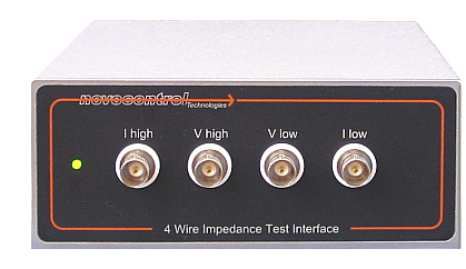
ZG4 has the same functionality as the ZG2 interface but two additional differential voltage measurement channels for 3 and 4 electrode measurements.
The voltage channel input impedance is 1012 Ω | 10 pF which exceeds the range of most competing instruments by several orders of magnitude and therefore can be seen as a major improvement in broadband 3 and 4 electrode measurements.
In order to reduce the capacity of the cables from the ZG4 voltage inputs to the voltage electrodes, the two voltage inputs support driven shield technology which keeps the potential of the outer coaxial cable shield at nearly the same potential as the sensitive inner cable conductor.
Like all Alpha-A test interfaces, ZG4 has high general purpose performance but is especially recommended for dielectric or conductive samples with
- significant electrode contact impedance or electrode sample interface polarization like e.g. electrolytes, liquids with ion conductivity (e.g. water based);
- low impedance samples below 1 Ω like e.g. strong electrolytes, heavily doped semiconductors, metals, superconductors;
- electronic components or networks.
ZG4 can be used with own sample cells for material measurements. It does not include a sample cell like the ZGS interface. For two electrode configurations, the BDS 1200 passive sample cell is recommended. The external interface design allows to locate ZG4 close to the sample in order to minimize cable effects. Cables in the sample impedance path may limit the usable high frequency range due to inductance and contribute low frequency noise for high impedance samples.
ZG4 Short Specification
| Ranges | |
| Frequency | 3 µHz ... 40 MHz (13.1 decades) * |
| Impedance | 10-4 .. 1014 Ω (16 decades) |
| Capacitance | 1 fF ... 10 F (16 decades) |
| Loss factor tan(δ) | 10-5 .. 104 |
| AC signal out | 100 µV .. 3 Vrms |
| DC bias out | −40 VDC .. +40 VDC, 70 mA max ** |
| Signal generator output impedance | 50 Ω |
| Voltage in | < ± 4.3 Vp dc or ac coupled |
| Differential Voltage Inputs with Driven Shields | |
| Input impedance | 1012 Ω | 10 pF |
| Common Mode Rejection |
< 10-4 below
100 kHz < 10-3 dB below 1 MHz |
| Input Bias Current | < 2.10-12 A |
| Base Accuracy | |
|
Relative Impedance, Relative Capacity, Loss factor tan(δ) |
< 3.10-5
*** |
| Phase Angle | < 2 m° *** |
| Resolution | |
|
Relative Impedance, Relative Capacity, Loss factor tan(δ) |
< 10-5 |
| Phase Angle | < 0.6 m° |
| User Calibrations | load, short, open, internal self calibration and diagnostics |
** requires dc bias option B of the Alpha-A mainframe
*** for details refer to specification charts