
ZGS
Test Interface with Active Sample Cell for Dielectric, Conductivity, Impedance Two-Electrode Spectroscopy for the Alpha-A Modular Measurement System
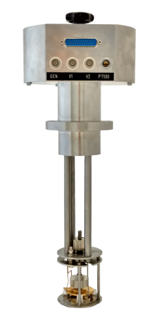
The ZGS extension test interface for the Alpha-A modular measurement system features high quality general purpose dielectric, conductivity, impedance spectroscopy and gain phase measurements. It the same functionality as the ZG2 interface, but is integrated in the head of a two parallel plate electrode sample cell similar to the passive BDS 1200 cell.
This arrangement avoids cables in the impedance path between the sample electrodes and analyzer input terminals. Cables may limit the usable high frequency range due to inductance and contribute low frequency noise for high impedance samples.
ZGS is specified at the sample electrodes position and therefore users do not have to care about artifacts by cell contributions to the measured results.
ZGS is therefore the optimal and turnkey solution for dielectric, conductivity and impedance material measurements between two parallel plate electrodes not requiring 3 or 4 electrode configurations.
ZGS contains a Pt100 temperature sensor and can be operated in combination with one of the Novocontrol temperature control systems between −160 °C .. 400 °C at the sample.
For most dielectric, conductivity and impedance measurements polarization or contact effects which can be partly compensated by 3 or 4 electrode techniques are less prominent. In this case, the standard configuration with the sample material prepared between two parallel plate electrodes as realized by ZGS is most advantageous.
This arrangement is easy to use and allows flexible sample preparation. Nevertheless, the sample cell design requirements for operating over a wide frequency, impedance and temperature range without sacrificing the Alpha-A system high accuracy are extraordinarily demanding.
ZGS Short Specification
(applies at the sample cell electrodes)| Ranges | |
| Frequency | 3 µHz ... 40 MHz (13.1 decades) * |
| Impedance | 0.01 Ω .. 1014 Ω (16 decades) |
| Capacitance | 1 fF ... 10 F (16 decades) |
| Loss factor tan(δ) | 10-5 .. 104 |
| AC signal out | 100 µV .. 3 Vrms |
| DC bias out | −40 VDC .. +40 VDC 70 mA max ** |
| Signal generator output impedance | 50 Ω |
| Voltage in | < ± 4.3 Vp dc or ac coupled |
| Base Accuracy | |
|
Relative Impedance, Relative Capacity, Loss factor tan(δ) |
< 3.10-5*** |
| Phase Angle | < 2 m° *** |
| Resolution | |
|
Relative Impedance, Relative Capacity, Loss factor tan(δ) |
< 10-5 |
| Phase Angle | < 0.6 m° |
| User Calibrations | load, short, open, internal self calibration and diagnostics |
* in combination with the Alpha-A mainframe type AT
** requires dc bias option B of the Alpha-A mainframe
*** for details refer to specification charts