
Electrochemical Impedance Spectroscopy EIS
In EIS one is frequently less
interested in the bulk sample material but especially in the properties
of the polarization layer at a metal to electrolyte or ion conductor
interface and the related chemical reactions. This is just the opposite
to dielectric,
conductivity or impedance material spectroscopy where these effects
are known as electrode polarization which is unwanted and tried to avoid
by e.g. 4-electrode
arrangements and particular cells.
The measurement set-up for a typical electrochemical 3-electrode
measurement is shown below.
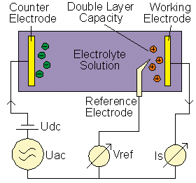
In addition to the two parallel plate electrodes (denoted as Counter and Working electrode), a third voltage reference electrode is placed close to the polarization layer and measures the voltage difference of the polarization double layer capacity to the working electrode. In contrast to dielectric, conductivity and impedance material spectroscopy where all electrodes are made of inert metal as e.g. gold, stainless steel or platinum, this applies for the electrochemical cell only for the counter electrode feeding current into the electrolyte.
The working electrode consists of the metal to be characterized in combination with the electrolyte. The reference electrode is usually an open tipped glass capillary filled with a standard electrolyte coupled to a standard metal in order to create a defined electrochemical potential to the electrolyte.
The total potential drop across the cell is summed up by all contributions of the chemical process like mass transport, chemical and adsorption steps, electron transfer, etc. By measuring the impedance spectrum VRef*(ω)/IS*(ω) and fitting it with an equivalent circuit model, the several process contributions can be separated from each other. The typical evaluation includes determination of Warburg impedance related to mass transport, electron transfer resistance, electrolyte resistance and double layer capacity.
As on the working electrodes an electrochemical reaction takes place, it is necessary to keep the DC potential VRef at a defined value or alternatively apply a constant DC current to the cell. This can be done by a Potentiostat / Galvanostat DC circuit as shown below.
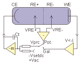
The voltage amplifier connected to CE electrode compares in potentiostat mode the differential voltage VPrc = VRE+ - VRE-- of both reference electrodes with the intended voltage VsetDC. The amplifier adjusts its output voltage until VPrc and VsetDC match resulting in a constant and sample impedance independent reference voltage differential which can be adjusted by Vsetdc. In galvanostat mode VPrc is created proportional to the measured cell current by a current to voltage converter (V<-I), resulting in constant sample cell current. In both modes, the variable capacitor Ct adjusts the control loop time constant in order to avoid free high frequency oscillations caused by too high open loop gain.
For impedance measurement an additional small AC voltage VAC is superimposed to VsetDC and the AC response is measured as according to fig. 2.
The two POT/GAL Test Interfaces for the Alpha-A modular measurement system are optimized for electrochemical impedance measurements of electrolytes with superimposed controlled voltage or current as described above.
The latest development for Electrochemical Impedance Spectroscopy is our new (2020) NEISYS Electrochemical Impedance System with its completely new and most versatile DETACHEM software.