
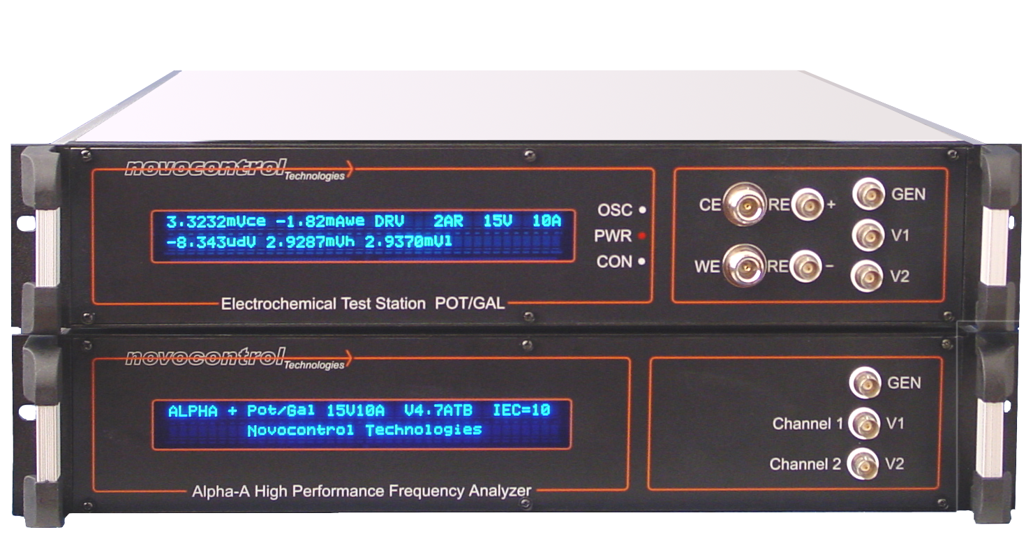
Alpha-A Analyzer
High phase and loss factor tan(δ) absolute accuracy for low loss dielectric materials and isolators broadband characterization
- phase accuracy of 0.002°
- tan(δ) accuracy of 3.10-5
It should be noted that absolute phase accuracy is required. Many manufactures specify instead phase resolution (the ability to separate two neighboring phase points) or phase range (the number of display digits) which both has no relation to absolute phase accuracy. In addition phase accuracy strongly depends on frequency and impedance. One should therefore compare specifications and typical results carefully.
An impedance analyzer measures both real and imaginary part of impedance. This is done by measuring at fix frequency ω/2π in addition to the amplitudes of sample voltage U(ω) and current I(ω) the phase angle φ(ω) between U(ω) and I(ω). From this, the complex impedance is calculated by

If both real Z’(ω) and imaginary part Z’’(ω) have similar magnitude, φ(ω) enters nearly linear in both. In this case phase accuracy is less critical. E.g. an accuracy of 1° in φ(ω) will limit the accuracy of Z’(ω) and Z’’(ω) to about 1% (of measured value) which is usually sufficient.
The situation changes, if Z’(ω) and Z’’(ω) differ by several orders of magnitude. This is often the case for dielectric samples or electronic components and always the case for low loss dielectrics, where the sample impedance is nearly only capacitive and φ(ω) ≈ -90°.
Nevertheless, one is interested in the small deviations from the ideal capacitive impedance and therefore both Z’(ω) and Z’’(ω) have to be measured. For φ(ω) ≈ -90°, Z’’(ω) is the major component which is due to sin(φ(ω)) ≈ -1 nearly insensitive to phase errors. On the other hand the minor component Z’(ω) mainly depends on φ(ω) as cos(φ(ω)) ≈ 0. The situation is graphically shown below.

It can be seen that the ratio of the Z*(ω) components which is
called power factor tan(φ)

is limited by the accuracy in the φ(ω) measurement.
More detailed, the phase error in φ(ω) enters with the multiplier of the power factor tan(φ(ω)) in the minor component of the measured impedance. E.g. for 1° phase accuracy the measurable ration tan(φ(ω)) would be limited to about < 100 meaning that Z’(ω) could not be measured at all if it deviates by more than two orders of magnitude from Z’’(ω). The other way around, a phase accuracy of about 0.01° would be necessary in order to measure Z’’(ω) with an accuracy of 1% for tan(φ(ω)) = 100.
Dielectric samples are usually represented by complex permittivity which is related to the measured impedance by

where C0 capacity of the empty electrodes. From this the ratio of the permittivity components which is called loss factor

Therefore, the same arguments for the ratio ε’’(ω)/ε’(ω) apply as for the impedance. Typical dielectric materials have loss factors tan(δ) from 10-3 .. 10-2, low loss dielectrics from 10-5 .. 10-3. With this, the requirements for phase measurement are extraordinary high.
E.g. a phase accuracy of about 0.001° .. 0.01° is necessary in order to measure ε’’(ω) of a typical dielectric material ( with tan(δ) from 10-3 .. 10-2) with 1% accuracy. For low loss materials, the question is usually not high ε’’(ω) accuracy, but whether it can be measured at all.